Home / Technical Guides

Engineering guide | Published 2026-10-01 | Reviewed 2026-10-01

RS-485 Modbus Meter Network Design Checklist

A stable Modbus meter network starts with the real device list, cable route, register maps, and required read interval. This guide helps BMS, metering, and controls teams turn those inputs into a network that can be commissioned and supported without guesswork.

By ConnectME Engineering. Reviewed by ConnectME Technical Services.

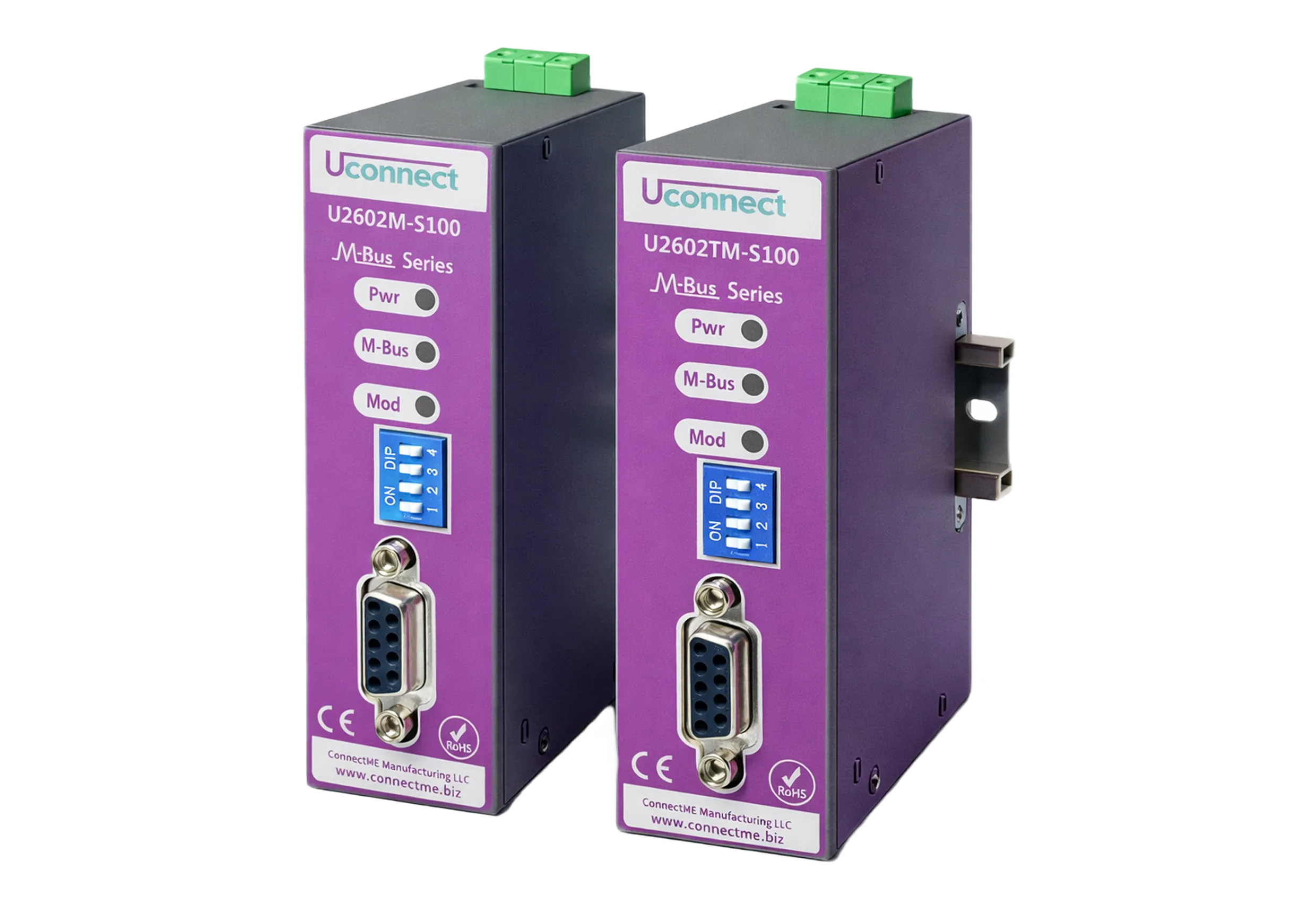
Industrial gateway and field network used for RS-485 Modbus meter integration

What a sound implementation requires

Design an RS-485 Modbus meter network by confirming every device interface and register map, using a controlled daisy-chain topology, assigning unique addresses and common serial settings, calculating the polling workload, and testing values and fault recovery at the final software destination. A device-count rule alone cannot prove capacity or reliability.

Written for

  • BMS and controls engineers
  • Metering and AMR system integrators
  • MEP consultants and commissioning managers
  • Facility OT and maintenance teams

Protocol roles, mappings, and design limits

Use this matrix to frame the architecture review, then verify the current specification and manufacturer implementation for the selected equipment.

Design input Record Why it matters Acceptance evidence
Device inventory Manufacturer, model, firmware, address, serial settings, location, and meter identity Prevents duplicate addresses and undocumented device-specific behavior Approved device schedule reconciled with installed labels
Register map Register, function, data type, word order, scale, unit, access, and valid range A valid response can still represent the wrong value when interpretation is incorrect Point-to-point comparison with the local meter display or approved reference
Physical network Cable type, route, segment length, shield practice, termination, biasing, and branch points Signal quality depends on the installed electrical topology and environment As-built drawing plus communication checks at representative ends of the segment
Polling workload Devices, register blocks, baud rate, response time, retries, timeout, and required refresh interval Determines whether the full cycle can complete with operational headroom Measured full-cycle time under normal operation and selected fault conditions
System behavior Stale threshold, quality flag, alarm, retry, recovery, and timestamp ownership Operations teams must distinguish a true zero from missing or stale data Witnessed loss-and-recovery test in the final BMS, AMR, or MDMS destination

Checks to complete before acceptance

1. 1. Freeze the source information

Do not size the network from a generic meter count.

  • Collect current manuals and register maps for the exact device models and firmware versions.
  • Confirm whether each device uses Modbus RTU over RS-485 and record baud rate, parity, stop bits, and address range.
  • List the required values and their operational use instead of polling every available register.
  • Assign a unique equipment identity that matches drawings, labels, software points, and billing records.

2. 2. Engineer the physical segment

Make the installed topology visible and maintainable.

  • Use the cable, topology, grounding, shielding, termination, and biasing practices required by the selected equipment and project design.
  • Avoid undocumented star branches and stubs; record any approved exceptions on the as-built drawing.
  • Separate or protect communication cabling from sources of electrical interference as required by the project and manufacturer instructions.
  • Provide accessible labels and isolation points so one device can be diagnosed without losing the network history.

3. 3. Calculate and configure polling

Size the cycle from transactions, not assumptions.

  • Group contiguous registers where the device permits it and avoid unnecessary high-frequency reads.
  • Estimate the normal cycle using request and response lengths, baud rate, device response time, inter-frame timing, retries, and timeouts.
  • Leave headroom for slow devices, transient faults, gateway processing, and future approved additions.
  • Document stale-value limits and the behavior expected when a device stops responding.

4. 4. Commission the complete data chain

Test the value where the operator will actually use it.

  • Compare local displays with gateway and application values for units, scaling, sign, decimal position, and word order.
  • Verify cumulative totals, rollover or reset behavior, timestamps, quality states, and communication alarms.
  • Disconnect a representative device where safe and witness timeout, stale indication, recovery, and any data backfill behavior.
  • Issue the register map, configuration backup, network drawing, test records, and support ownership at handover.

How the checks apply in real projects

Energy meters to a BMS

Poll only the approved energy, power, demand, status, and diagnostic blocks needed by the BMS. Map each register to a named point with a unit and quality state, then compare representative values with the meter display before accepting graphics or trends.

Mixed-brand meter retrofit

Different meters can share the same physical segment when their serial settings and electrical requirements are compatible, but each register map remains device-specific. Normalize the destination points without hiding the source model or diagnostic context.

Slow or unstable segment

Capture which devices time out, how retries affect the full cycle, and whether the issue follows a device, cable section, or gateway port. Reducing the polling rate can mask an electrical or configuration fault, so diagnose the cause before treating it as a capacity problem.

Limits and project responsibility

  • RS-485 electrical limits, device loading, cable length, and serial timing depend on the selected transceivers, equipment, cable, environment, and manufacturer instructions.
  • The Modbus protocol does not define the meaning of a vendor's register map; use current model-specific documentation and approved project mappings.
  • Writable registers, remote commands, network segmentation, and remote access require project-specific controls and OT cybersecurity review.

Primary references

Related ConnectME resources

Technical guide FAQ

How many Modbus meters can share one RS-485 network?
There is no reliable universal number. Capacity depends on the transceiver loading, device and gateway limits, addresses, cable and topology, baud rate, registers per device, response times, retries, and required refresh interval. Calculate and then witness the complete polling cycle with headroom.
Why does a Modbus meter return data that looks incorrect?
Common causes include the wrong register version, data type, signed interpretation, word or byte order, multiplier, engineering unit, or register offset. Compare the exact model documentation and a local meter value before changing software scaling.
Should Modbus meters be wired in a star or daisy chain?
RS-485 field networks are normally engineered as a controlled bus or daisy chain. Branches, stubs, termination, biasing, shielding, and grounding must follow the selected equipment and project design rather than a generic diagram.

Discuss the project requirement with ConnectME